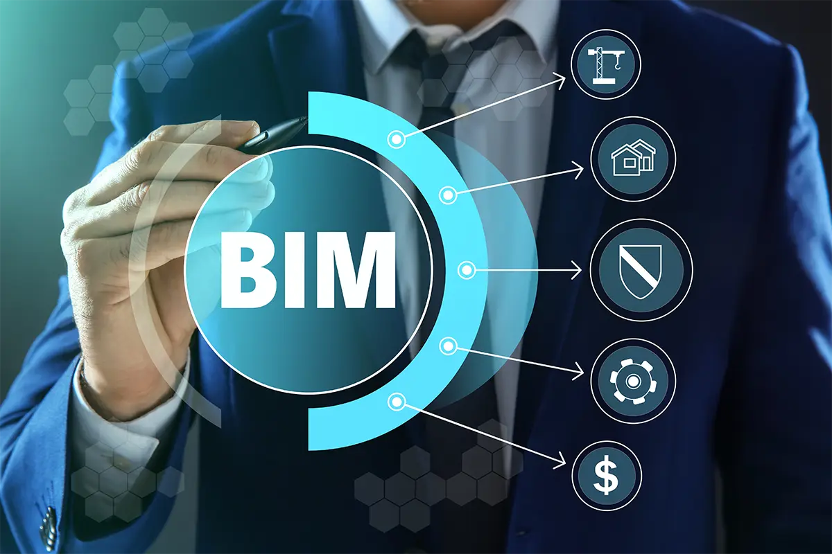
Building Information Modeling (BIM) is the practice of designing and constructing a building through a shared 3D digital model rather than through separate sets of drawings. Every element in the model, from a column to a duct, carries data: its size, material, location and its relationship to the elements around it. Because the model is shared, the architect, the structural engineer, the mechanical, electrical and plumbing trades, the general contractor and the fabricators all work from the same source of information instead of comparing 2D drawings by hand.
BIM coordination is the part of that practice where the models from every design discipline and construction trade are combined into one federated model, checked for conflicts, and corrected before anything is fabricated or installed. A 900 mm (36 in.) duct main that runs through the web of a transfer girder is caught on a screen months before erection, and the decision to move the duct, reinforce the girder or reissue the steel is made while the fix is still a change in a model rather than a change on site. In a McGraw Hill Construction SmartMarket Report on the business value of BIM, 82 percent of U.S. contractors surveyed said they used BIM for multi-trade coordination, one of the most common BIM uses on U.S. jobsites.
This guide explains how BIM coordination works when structural steel is in the model, why steel sets the pace for every other trade, what level of development the steel model needs at each milestone, and what to ask a fabricator before you award the package. We write it as American Katerra, LLC, the U.S. subsidiary of Yamaguchi Heavy Industries Ltd., which delivers steel detailing and BIM services in Tekla Structures with every fabrication package.
What Is BIM Coordination?
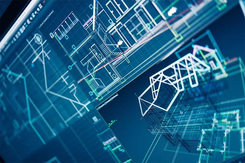
BIM coordination is the structured process of aligning the models of all project participants so that the building can be built as modeled. Each discipline (architecture, structure, mechanical, electrical, plumbing, fire protection) models its own scope. A BIM coordinator combines those models into a federated model, runs clash detection, assigns each conflict to the party responsible for it, and tracks it to resolution. The BIM Project Execution Planning Guide from the Penn State Computer Integrated Construction Research Program, a widely used reference for U.S. BIM execution plans, calls this BIM use “3D Coordination” and describes it as a process in which clash detection software is used to determine field conflicts by comparing 3D models of building systems.
Coordination is a management process that happens to use software. The software finds the overlaps; people decide who moves, by how much, and at whose cost. A project can run the best coordination platform available and still coordinate badly if the models arrive late, at the wrong level of development, or on different coordinate systems.
BIM Coordination vs. Clash Detection
Clash detection is one step inside BIM coordination. The software compares model elements and reports three kinds of conflict. A hard clash is two objects occupying the same space, such as a pipe passing through a beam. A soft clash, or clearance clash, is two objects that stay apart yet violate a required clearance, such as a duct that leaves no room to swing a wrench on a bolted connection, or a ceiling that leaves no space for the specified fireproofing thickness. A workflow or 4D clash is a sequencing conflict: the steel can be erected as modeled, but the crane path or the delivery order makes it impossible on the planned date. Clash detection produces the list. Coordination is the work of prioritizing that list, deciding who moves, and confirming the fix in the next model issue.
Who Does What in BIM Coordination
The owner sets the requirements, usually through a BIM exhibit such as the AIA G202-2013 Project BIM Protocol Form and a BIM execution plan (BEP). The general contractor’s BIM coordinator or VDC manager runs the process: assembling the federated model, running clash tests, hosting the coordination meeting and keeping the issue log. The engineer of record provides the design model and the fabricator’s steel detailer builds the fabrication model. AISC 303-22, the Code of Standard Practice for Steel Buildings and Bridges, defines the first as the three-dimensional digital model of the structure that conveys the structural steel requirements, and the second as the three-dimensional digital model produced to convey the information necessary to fabricate the structural steel. The detailer brings the fabrication model to coordination alongside the fabrication-level models of the mechanical, electrical, plumbing and fire protection trades, and the erector reviews the erection sequence against the federated model.
Why Structural Steel Anchors the Coordination Process
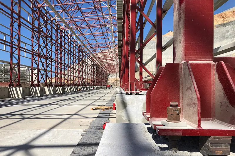
Structural steel is the skeleton of the building, so every other system routes around it. Ducts, pipes and cable trays bend to miss beams; equipment sits on framing that must be in the right place; curtain wall and cladding attach to spandrels and embeds that the steel detailer locates. This makes the steel model the reference the other trades coordinate against, and it is usually the first trade model to reach fabrication-level detail. Steel also carries a long lead time: mill orders, detailing, approval and fabrication run months ahead of erection, so steel is often released for fabrication before mechanical and electrical routing is final. A change to steel after release costs more than a change to a duct, because plates have been cut, holes drilled and pieces welded to the released model.
The clashes that involve steel tend to fall into a short list:
- Penetrations through beams and girders: ducts, pipes and conduit that need a web opening, which the engineer of record must approve and may need to reinforce.
- Connection clearances: gusset plates at braced frames, stiffeners at moment connections and bolt access at beam-to-column joints, none of which appear in a design model that shows only member centerlines.
- Interfaces with concrete: anchor rods and base plates against foundation rebar, embed plates in walls and slabs, and shear studs against deck edges.
- Framing below equipment: rooftop units, mechanical mezzanines and elevator machine rooms, where support steel must line up with equipment rails.
- Stairs, platforms and miscellaneous metals, which run through the same shafts and corridors as the MEP mains.
- Fireproofing: spray-applied fireproofing adds thickness to every member and is a frequent source of clearance clashes with ceilings and MEP.
Most of these conflicts become visible only once the steel model carries connections. That is why the level of development of the steel model matters more than the software used to view it.
The BIM Coordination Process, Step by Step

A typical BIM coordination process for a steel-framed building runs in six steps. The order matters less than the discipline of finishing each step before the next milestone.
Step 1. Set the Rules in the BIM Execution Plan
The BEP records who models what, to which level of development, by which milestone and in which format. For steel it should name the model element author for each phase (the engineer of record for the design model, the fabricator for the fabrication model), the shared coordinate system and project origin, the grid and level naming, the units, the exchange format (usually IFC, the open format published by buildingSMART and standardized as ISO 16739), the clearance rules for clash tests and the meeting cadence. Settling these points early prevents the most common failure in coordination: two trades modeling on different origins and generating thousands of false clashes.
Step 2. Build the Steel Model to the Right Level of Development
The engineer of record’s design model typically reaches LOD 300: members are specific in size, shape, location and orientation. Coordination needs LOD 350. The BIMForum Level of Development Specification, whose current edition is the LOD Spec 2025, defines LOD 350 as a model element represented in terms of quantity, size, shape, location, orientation and interfaces with other building systems. For structural steel, the Specification’s interpretation puts base plates, gusset plates, anchor rods, web stiffeners and sleeve penetrations at LOD 350, and adds welds, copes, cap plates, washers and nuts at LOD 400. The fabricator’s detailer builds that content in steel detailing software. American Katerra models in Tekla Structures, where the same model later generates shop drawings, erection drawings and CNC data. Our structural steel fabrication page explains how that single model carries the package from detailing to erection.
Step 3. Federate the Models
Each trade exports its model, usually as IFC, and the BIM coordinator combines the exports into one federated model on the common origin. The steel fabrication model goes in early and is reissued on an agreed schedule as detailing progresses, typically by area or level, so that the MEP trades can start routing against coordinated steel without waiting for the whole frame.
Step 4. Run Clash Detection and Triage the Results
Clash tests run system against system, such as steel against mechanical, with the clearance rules from the BEP. The raw list is always long, and much of it is noise: intended penetrations, elements that will be trimmed in the field, and duplicates. The coordinator groups clashes by location and system, removes the false positives, ranks the rest by the cost of fixing them late, and assigns each one to an owner. Issues move between software tools in the BIM Collaboration Format (BCF), the buildingSMART open standard that carries a screenshot, the model coordinates and the IDs of the affected elements, so that a clash found in the coordination platform opens in the detailer’s Tekla model at the same spot.
Step 5. Hold the Coordination Meeting and Close the Loop
The BIM coordination meeting, usually weekly, walks the model by zone and level. Each open clash gets a decision: the duct moves, the beam gets an approved penetration, or the question goes to the engineer of record as a request for information (RFI). The steel detailer should be in the room whenever steel is on the agenda. Only the detailer knows what a change costs in the fabrication model, and a decision that looks free in a viewer, such as shifting a beam 50 mm (2 in.), can move a column base, a brace work point and every connection along the line. Every decision is logged against the affected piece marks, and the fabrication model is updated before the next issue.
Step 6. Sign Off, Release for Fabrication and Control Changes
When a zone is clash-free to the agreed tolerance, the trades sign it off and the steel for that zone is released for fabrication. From this point the fabrication model is under change control: a revision requires a formal issue, a revised approval and a new drawing revision, and each change is traced back to the coordination log. Erection sequencing is coordinated in the same model, which, when linked to the schedule, becomes a 4D model that checks crane picks and delivery order against site logistics.
What "Coordinated" Means for Steel: LOD 350 vs. LOD 400
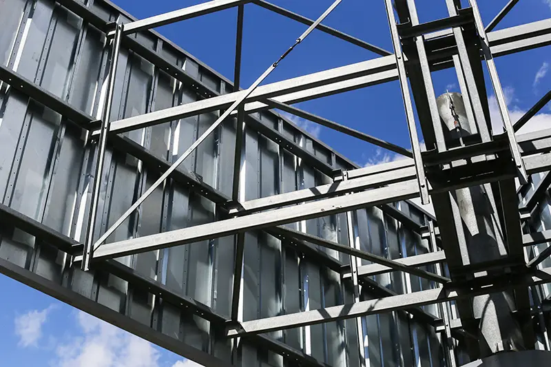
The most common misunderstanding between general contractors and steel fabricators is what the words “coordinated model” mean at each milestone. A design model at LOD 300 shows where members are; it does not show the plates, bolts and stiffeners that occupy the space around them. A model at LOD 350 shows those interfaces, and that is the level BIM coordination needs. A model at LOD 400 carries everything needed to fabricate, and that is the level from which shop drawings are produced. AISC 303-22 defines the fabrication documents as shop drawings, a fabrication model, or a combination of the two, so a LOD 400 model can itself be part of the approved documents when the contract documents say so. Ask for LOD 350 at the coordination milestone and LOD 400 at the approval submittal, and write both into the contract. Our companion article on steel detailing and shop drawings covers who owns each model and what engineer approval does and does not mean.
How BIM Coordination Pays Off
The Penn State guide lists the value of 3D coordination as reducing field conflicts and RFIs, visualizing construction, increasing productivity, reducing cost growth from design coordination, decreasing construction time and enabling prefabrication. Contractors’ own reports point the same way: in the McGraw Hill Construction report cited above, 40 percent of contractors with very high BIM engagement said BIM had significantly reduced rework on their projects. For a steel package the mechanism is simple. Every clash resolved before release for fabrication is a piece that is not re-cut, a hole that is not field-drilled and a crane hour that is not spent waiting.
A coordinated fabrication model also produces information that outlives the coordination meeting. Quantities taken from it drive cost estimating, and the same member list, weights and grades feed the embodied carbon and life cycle assessment calculations that owners increasingly require. Our guide to life cycle assessment in steel construction and our embodied carbon page show what that documentation looks like, and our Green Information Modeling™ approach rests on the same principle: one model for geometry, cost and carbon. Downstream, the same geometry drives offline programming for robotic welding.
Seven Questions to Ask a Fabricator About BIM Coordination

Coordination quality is decided at award. These seven questions take ten minutes in a bid interview and tell you how a fabricator will actually behave in the coordination meeting.
- Who represents you in coordination meetings, and is that person the detailer working on our model?
- What software do you model in, and can you deliver IFC exports and receive BCF issues?
- What level of development will your model reach at the coordination milestone and at the approval submittal?
- How do you reissue the model as detailing progresses: by zone, by level, and on what cadence?
- How is a coordination decision recorded in your model and traced to piece marks?
- What happens to a clash found after release for fabrication, and how is the change priced and approved?
- Will connections be modeled in time for coordination, or only after connection design is complete?
American Katerra’s answers: our detailing and BIM team models in Tekla Structures and exports IFC for federation; a named detailing lead attends coordination; LOD by milestone is written into the contract; every decision, RFI and revision is logged against piece marks; and connection geometry is modeled ahead of the coordination issue rather than after the approval set. Our detailers train through the National Institute of Steel Detailing; our article on NISD membership explains what that means, and our careers page lists current BIM and detailing openings.
FAQ: BIM Coordination

What is BIM coordination in construction?
BIM coordination is the process of combining the 3D models of all design disciplines and construction trades into a federated model, detecting conflicts between them, and resolving those conflicts before fabrication and installation. It is run by a BIM coordinator, usually on the general contractor’s team, through clash detection and regular coordination meetings.
What does a BIM coordinator do?
A BIM coordinator sets up the federated model, runs clash detection between trade models, filters and prioritizes the results, assigns each clash to the responsible party, hosts the coordination meeting and maintains the issue log until every clash is resolved and the zone is signed off.
What is the difference between BIM coordination and clash detection?
Clash detection is a software test that finds where model elements overlap or violate clearances. BIM coordination is the wider management process that includes clash detection, the meetings where conflicts are resolved, the RFIs raised to the designers and the change control after sign-off.
What LOD is needed for BIM coordination?
LOD 350, as defined by the BIMForum Level of Development Specification, is the level at which model elements include their interfaces with other building systems. For structural steel that means connections, base plates, gusset plates, anchor rods and stiffeners. LOD 400 adds fabrication detail such as welds and copes and is the level used for shop drawings.
Which software is used for BIM coordination?
Each trade models in its own tool, such as Tekla Structures for structural steel, and exchanges models as IFC. The federated model is reviewed in a coordination platform that runs clash detection, and issues are exchanged in the BCF format. Agreeing the origin, formats and clearance rules in the BIM execution plan matters more than the choice of platform.
Talk to Our Detailing and BIM Team
If you are planning a steel-framed project and want the steel coordinated before it is cut, we can help. Our steel detailing and BIM services team models in Tekla Structures, coordinates with your other trades, attends your coordination meetings, and will put LOD by milestone, reissue cadence and change control in writing for your project. Send us your drawings or model through our contact page, and we will show you how we would detail and coordinate the steel.